


$382.00 – $480.00Price range: $382.00 through $480.00
Designed for emergency rescue, linesmen, tree surgeons, electricians and trained personnel for the determination of “Live and Dead” situations in many fields for safety purposes and life threatening situations.
G.L McGavin have been manufacturing High and Low voltage testers since 1975. The new G.L McGavin Digital hand held Proximity Tester AC30 is designed for Electricians, Technicians and the Fire & Rescue departments. For electricians it can be used for picking up live wires behind walls, identifying live cables and tracing live cable runs. For the Fire and Rescue it is used for the safety of the rescue personnel in situations where live voltage can be present impeding rescue operations. Because it is a Digital device it can be programmed to suit any application.
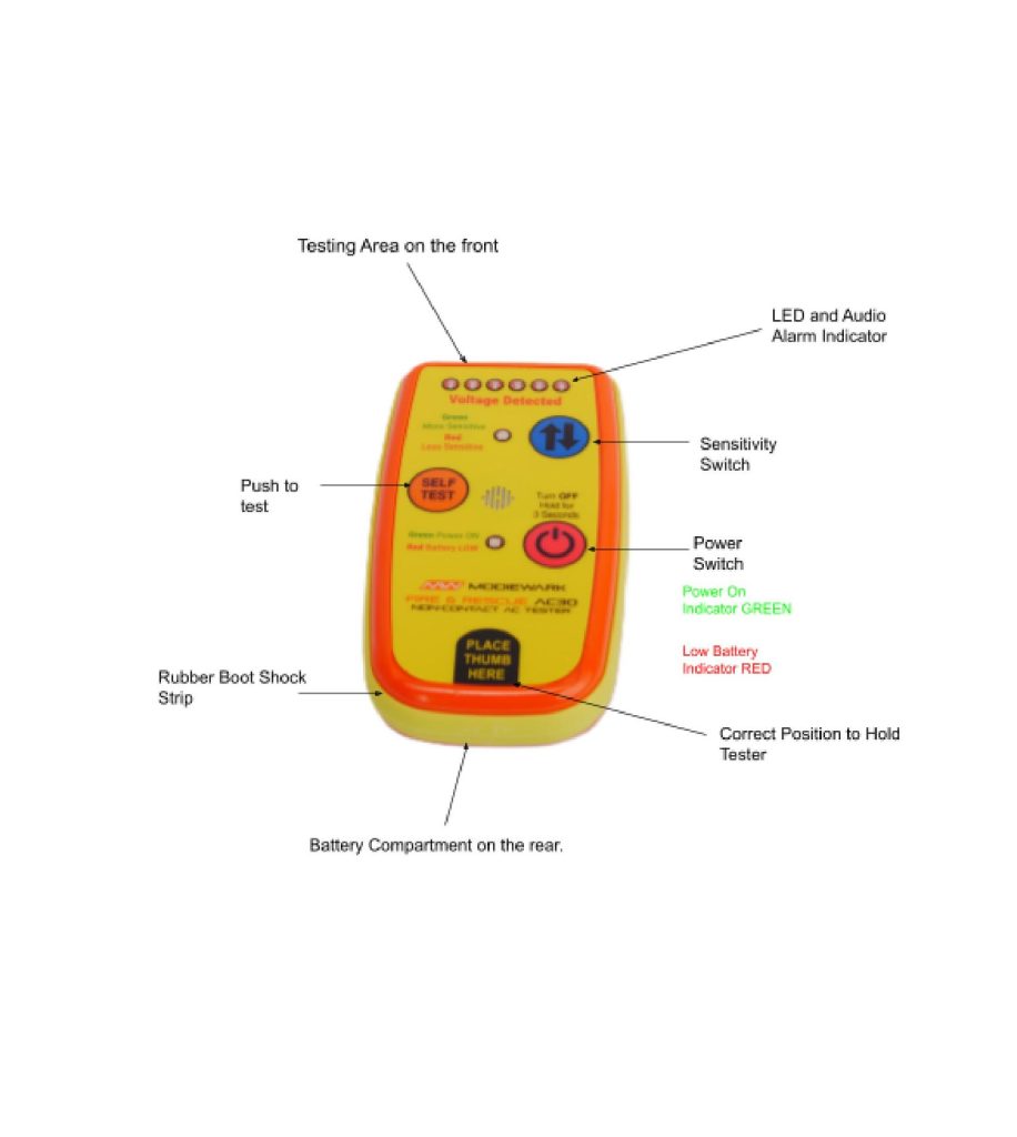
When the unit is activated using the ON switch the unit will self test automatically ensuring the unit is in working order. The Self Test button is located on the front face of the tester. This is a full function test of all components of the unit testing:
The self test button is recommended to be used at regular intervals during the working day. In the event the tester fails please refer to (Service and trouble shooting).
The Self Test feature is designed as an independent circuit, apart from the detection circuit. This Self Test circuit produces an AC signal that the detection circuit can pick up, as it would pick up an outside signal source. This allows confidence that the AC30 Non-contact AC Voltage Tester is working correctly.
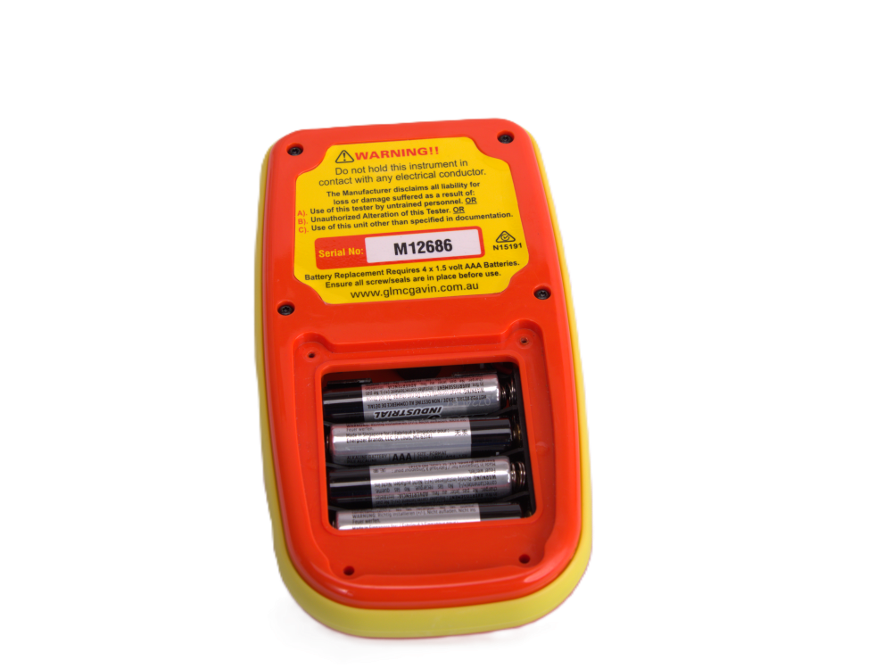
The Battery is located on the rear of the tester and requires 4 *AAA 1.5 volt Alkaline or Lithium Batteries. The Battery compartment located on the back of the unit requires a Phillips head screwdriver to remove the four screws holding the battery cover.

Ensure the battery is fitted the correct way placing the positive terminal as indicated on the inside base of battery compartment.
To place the battery lid back into place a Phillips head or star screwdriver is required. Insure the o-ring is fitted in the grove as shown above. Using Two Short Screws (M2*5mm) on the top two holes and two Long Screws (M2*8mm) on the Bottom two holes. Screw until firm do not over tighten.

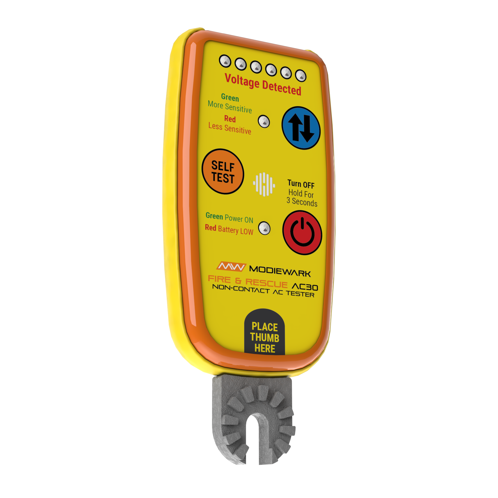
This switch allows changes to the sensitivity of the AC30.
When the GREEN Indicator is ON the unit is set to the highest sensitivity setting, It is expected to detect 7,000 volts to ground outdoors 15 meters away and detect 240 volts 2-3 meters away.
When the RED Indicator is ON the unit is set to the lowest sensitivity setting It is expected to detect 7,000 volts to ground 5 meters outside and detect 110 volts inside at 250 mm away from an active GPO. (These Setting can be changed on request)
When the unit is activated using the ON switch the unit will self test automatically ensuring the unit is in working order.
The Self Test button is located on the front face of the tester. This is a full function test of all components of the unit testing:
The self test button is recommended to be used at regular intervals during the working day. In the event the tester fails please refer to (Service and trouble shooting).
The Self Test feature is designed as an independent circuit, apart from the detection circuit. This Self Test circuit produces an AC signal that the detection circuit can pick up, as it would pick up an outside signal source. This allows confidence The Rescue FR30 is working correctly.
| Voltage sensing range | 20 volts AC to 500 K volts AC |
|---|---|
| Light source | High intensity LED |
| Sound Source | Piezo 4000KHz 90 dB @ 10cm (3.937’) |
| Operating temperature | -20 to 65˚C (14 to 149°F) |
| IP rating | IP 66 (Testing not Completed) |
| Weight (no Batteries) | 140g (4.93 oz) |
| Dimensions | L 40 mm (5.51’) x W 73 mm (2.87’) x H 23 mm (0.9’) |
| Battery | 4* AAA Alkaline / Lithium |
| Battery life (AAA Alkaline) | ON (no alarm) 30+ Hours ON (alarm on) 8+ Hours OFF 3 Months |
| Battery life (AAA Lithium) | ON (no alarm) 40+ Hours ON (alarm on) 10+ Hours OFF 3 Months |
| Shock Proof | Rubber mount around case |
| Self test | Independent Built in |
| Belt clip (option) | Attached to rear of case (Customer Request) |
| Range detection | LED Indication Weak Signal to Strong signal. |
| Voltage range | Two Settings Less sensitive and More sensitive. |
| Large buttons | 15mmØ for Glove operations |
| Secure battery housing | (fours crews) Tool Access |
| Custom colours | On Customer Request |
| Custom decals | On Customer Request |
These values are estimates within 90% for prototype specs.
In the event a vehicle is the cause of damage to a power pole or any emergency situations, the result may bring down the attached lines. These lines are active and the surrounding area can be energised. A HAZARD AREA must be established until electrical authorities disconnect power.
If power lines are broken the two halves of the line are still energised and a safe distance must still be maintained from both sections or electrocution could occur.
Always assume the conductor is alive until proven de-energised.
Do not touch wire or car as you could experience ground potential (shock).
On the arrival at a structure fire, identification of power lines and connection to property must be located and identified; procedures for active live power isolation and disconnection should be followed.
When circumstances require access to the property before power has been disconnected use the GLM MINI to determine live power areas. Examples of the areas are:
Placing a metal ladder against the metal gutter
Upon entering a property
NOTE: Because the property is still live the high setting on the GLM MINI may be detecting other voltage sources such as wires in the roof or walls or the adjacent property. To overcome this use the low setting on the detector and more accurate location of AC voltage sources can be determined. By placing your hand in the middle of the unit not covering the front test area label, sensitivity is decreased providing an accurate location of voltage.

The voltage to a property may be officially disconnected by supply authority. This may not always be the case as faults in the electrical network may cause residual voltages to be carried in water pipes and neutral link connections. Suspect locations such as those involving drugs may be acquiring power from neighbouring locations or generator units these supplies may not be disconnected. These voltages may be low but the current high. Use the GLM MINI to verify voltage at all instances.
Structures such as these contain voltage sources and can be detected by the GLM MINI using the above procedures.

In all natural disasters electricity is a major concern, as fallen power lines and water make a dangerous mix. The GLM MINI can be used in all of these situations.
The GLM MINI will not detect submerged power cables as water decreases the electromagnetic field generated.
In all emergency situations, always assume line is energised on initial test. Never assume de-energised lines will remain in that state.